Introduction to the Wireless Modbus Module #
Overview of the Modbus Protocol #
Modbus is an application-layer messaging protocol, designed in 1979 by Modicon, which facilitates master/slave interaction between devices. A de facto communication standard in industrial electronics, it has the following features:
- Master-Slave Architecture: One master device issues commands to one or more slave devices that respond in kind.
- Data Representation: Modbus categorizes data as either coils (binary) or registers (numeric), offering diverse data manipulation capabilities.
- Variants: Modbus has adapted to different environments with variants like Modbus RTU, Modbus ASCII, and Modbus TCP/IP.
The RS485 Communication Standard #
RS485, or EIA-485, prescribes electrical specifications for drivers and receivers in digital multipoint systems. It is characterized by:
- Extended Communication Range: Capable of transmitting data up to 4000 feet (~1200 meters).
- Noise Resistance: Differential signaling provides robustness against voltage fluctuations and electromagnetic interference.
- Multi-Drop Configurations: Supports up to 32 devices on a single bus network.
RS485’s reliability is a cornerstone of industrial controls in leveraging Modbus protocol.
Connection #
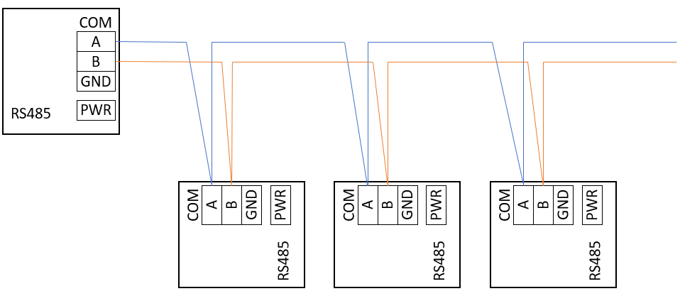
RS485 Connection #
A standard RS485 wiring diagram depicting a “daisy-chain” topology is shown:
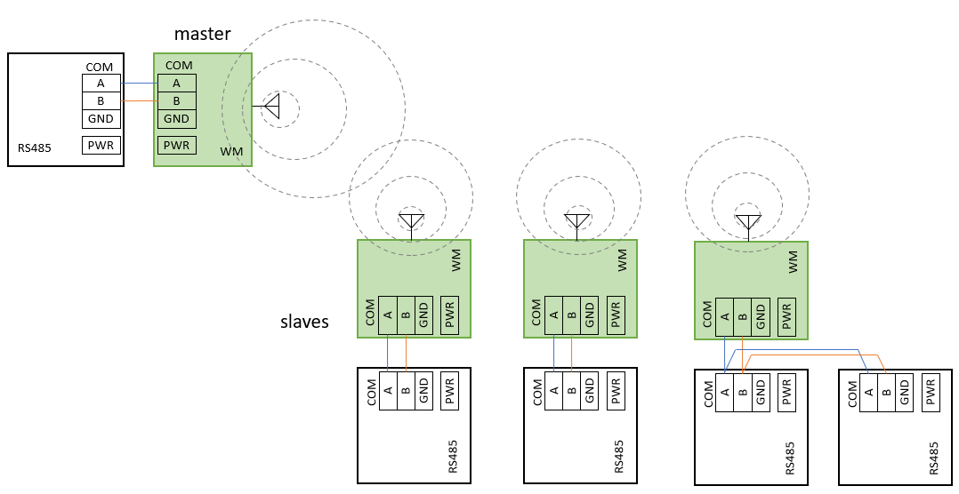
Connection of the Wireless Modbus #
Replacement of wired RS485 connections with a wireless module:
Features of the Wireless Modbus Module #
Firmware version 0.2
The module supports baud rates [in bps]: 1200 to 1000000, including automatic master node baud rate detection and synchronization.
Communication Between Master and Slave #
The interaction comprises the master’s request, the slave’s response, and the corresponding response times as shown:
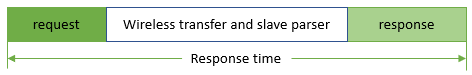
Example timing for a 69-byte request and 8-byte response Modbus RTU query. Response timing across UART and wireless PHY settings:
| UART Settings | Net PHY Speed | Response Time [ms] |
|---|---|---|
| 4800-8-1-E | 1M | 222 |
| 9600-8-1-E | 1M | 127 |
| 14400-8-1-E | 1M | 94 |
| 19200-8-1-E | 1M | 76 |
| 115200-8-1-E | 2M | 28 |
| 500000-8-1-E | 2M | 17 |
Configurations and User Interface #
Configuration channels include ATCMD, UART-based commands, physical interfacing (buttons/switches), and upcoming BLE.
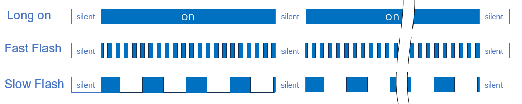
LED Indicators #
Two LEDs (Blue and Red) denote operational states. Patterns of their light signify network status and the network node mode. It varies as follows - fast flash, slow flash, and constant on. For example:
| State | LED Activity | LED Interval |
|---|---|---|
| Network Loss | Fast flash: 100ms on/off | 500ms off |
| Network Sync | Continuous: 3sec on | 500ms off |
| Network Wait | Slow flash(500ms on/off) | 500ms off |
Dip Switch Configuration #
Settings like SW1 and SW2 determine network status and node mode, respectively.
Setting RS485 parity with SW3 and SW4.
| Switch | Function | Description |
|---|---|---|
| SW1 | Network start/config | On: Activate; Off: Default. See below. |
| SW2 | Node mode | On: Master; Off: Slave. |
| SW3 | RS485 parity enable | On: Enable parity; Off: Disable parity |
| SW4 | RS485 parity mode | On: ODD Parity; Off: EVEN parity |
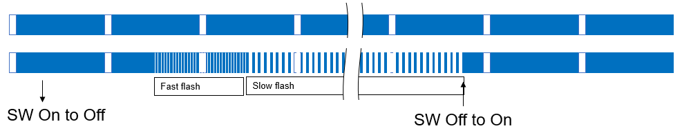
SW1 Configuration Details
- ON to OFF: Trigger reconfiguration; a fast flash indicates readiness to reconfigure.
AT Commands #
Each command starts with AT and ends with a terminator. The command and response bodies vary by read parameter or result code.
Normal AT Commands #
| Command | Response | Description |
|---|---|---|
| AT+MODE=?, | +MODE=[m,1,0] | Read the device Mode. m: 1, master; 0, slave. |
| AT+STATE=?, | +STATE=[x,p,ch] | Read net state. x:1, sync; 0, loss. p: phy. ch:channels |
| AT+UART=? | +UART=[baud,data,stop,parity,th] | Read RS485 UART setting. baud:baudrate; data:data bits(8); stop: stop bits(0: 1bit, 1: 2bits), parity:(0:disable, 1: odd, 2: even); th: internal threshold. |
| AT+PKTL=?, | +PKTL=[up,dn] | Read data packege size. up: uplink size; dn: downlink size |
| AT+PKTL=[up,dn], | Result code | Write data packege size. up: uplink size; dn: downlink size |
| AT+LOG=x | Result code | Write Log enable level x: bit[0:2]. 3 levels |
| AT+ADDR=? | +ADDR=[xxyyxxyy] | Read net address. xxyyxxyy: address |
| AT+ADDR=[xxyyxxyy] | Result code | Write net address. xxyyxxyy: address. sendAT+SYSCMD=3save config and sendAT+SYSCMD=1 to apply |
| AT+VER=? | +VER=[xxH] | Read firmware version |
| AT+NET=? | +NET=[p,t,d,u] | Read net information. p:phy, t: type, d:downlink length; u:uplink length |
| AT+SYSCMD=x | Result code | Send system command. x: 1, reset; 2, restore; 3, save config. |
Responses follow the <CR><LF> structure.
Result Codes #
Result codes for command outcomes:
0for success,0x1001for Command execution error0x100Afor Bad command0x100Bfor Bad format0x100Dfor Bad parameter0x100Efor OvertimeOthersfor Protocol stack error
Advanced Commands #
There are also advanced commands for specialized tasks.
For detailed information, consult the Engineer’s Manual.