AOA Antenna #
Overview #
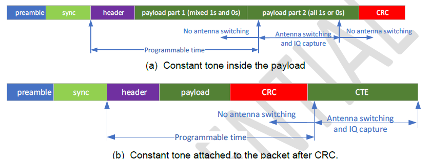
AOA Antenna engine supports antenna switching and IQ capture,as shown in the following Figure.AOA Antenna engine supports IQ capture for constant tone inside the payload and attached to the packet after CRC.

Below are some key features of the AoA antenna switching IQ capture engine:
- Programmable SYNC address (preamble is not programmable)
- Programmable channel index and frequency relationship
- The enable/disable of whitening is programmable (the whitening sequence is not programmable, it is decided by the channel index)
- Support up to 256 antenna patterns.
- The antenna pattern can be directly to control the outputs of 8 GPIOs.
- Programmable starting time for IQ capture and antenna switching (as shown in above figure)
- Programmable antenna switching pattern
- Programmable duration for each antenna (in terms of how many clock cycles of a 2MHz clock)
- 4 programmable capture speeds: 8, 4, 2 and 1 MSPS
- Capture length is up to 8192 IQ samples (For 8 MSPS IQ capture speed, it means we can capture IQ samples up to 1024 us).
- Two programmable raw IQ capture word length: 14-bit and 12-bit in 2’s complement.
- Readable IQ capture status: the starting address in capture memory and length
- Two AGC operation modes (SW programmable)
- Freeze after SYNC is found
- Always adjust the gain according to the input signal level
- IQ and Antenna switching for constant tone inside the payload (before CRC) or after CRC
Design Details #
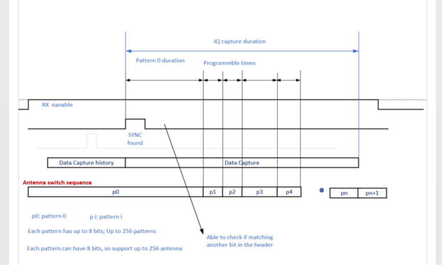
The following Figure shows the AoA antenna switching and IQ capture scheme. The AoA captured is controlled by the AoA controller. Once the controller detects a valid special signal (by matching the sync address that user has programmed), the controller uses the SYNC valid signal to generate various RX antenna switching signals and automatically captures the IQ samples.
Antenna Switch #
AOA Antenna engine support a sequence of RX antenna switch signals as shown in the above figure, which have the following feature:
- The sequence consists of multiple 8-bit patterns (up to 256 patterns).
- Each of bit of a pattern can be mapped to an GPIO output.
- The sequence can have up to 256 patterns.
- Each pattern has its own programmable duration (10-bit, unit 0.5us).
The sequence consists of:
- Pattern 0 and its duration
- Pattern 0 is the default antenna pattern, and it is used upon RX enabled.
- Pattern 0 duration: This duration is measured starting from SYNC found.
- Pattern 1 and Pattern 1 duration
- Pattern 2 and Pattern 2 duration
- ……
- The last pattern and the last pattern duration
- The last pattern duration is a don’t care, it means the pattern will be used until the end of the RX regardless of the time being programmed.
All the above durations have a unit of 0.5us and can be up to 511.5 us. If the specified duration is 0, it means that the corresponding antenna will be used until the end of RX.In normal case, if SYNC is found, then the antenna switch will be always like (Pi denotes pattern i).P0, P1, P2, …, PN. If the received signal is not good (like SYNC is not found), the switching may end early and stop before PN where PN is the last pattern.
IQ Data Capture #
Once RX is enabled, IQ data along with the used antenna pattern are captured into memory if AoA is enabled. The captured data are written into memory in a circular way. If the address reaches its maximum, the address wraps around.
Once a SYNC is found, the address holds the captured data when SYNC found happens is written into a status register which user can access. The IQ capture keeps going until the IQ capture duration expires.The IQ capture can be captured starting from SYNC found or be captured since RX is enabled. In the first case, the memory with address offset of 0 holds the IQ capture when SYNC is found. In the second case, there is a status register which tells us the address offset of the IQ capture when SYNC is found.
Each IQ capture occupies 4 bytes, the device supports up to 8192 IQ captures. The IQ capture can be captured at a speed of 8 MSPS, 4 MSPS, 2MSPS and 1 MSPS (user programmable).
Bit-patten match and mask #
AOA Antenna engine also supports a feature that only if both SYNC match and some of bits in a 32-bit sequence match, the device starts to do AoA antenna switch and IQ capture.
- If this feature is enabled, besides the SYNC, the AoA antenna switch and IQ capture also rely on the received bits. The user can program where the 32-bits starts (i.e., the bit position offset in following figure), the 32-bit pattern which user want to let the hardware to compare with the received bits. In addition, the user can program a mask in case only some selected bits in the 32-bit pattern need to be matched.

API #
initialization. #
typedef struct aoa_cap_ant_pattern_s
{
    uint16_t duration;
    uint8_t addr;
} aoa_cap_ant_pattern_t;

typedef struct aoa_cap_filter_s
{
    int8_t enable;
    int8_t channel;
    uint32_t bit_pattern; //B0 is header[0];B1 is header[1];B2 is address[0];B3 is address[1]
    uint32_t bit_mask;
} aoa_cap_filter_t;

const aoa_cap_ant_pattern_t *patterns is antenna switch pattern,
int size is size of patterns, maximum is 256,
aoa_cap_filter_t *filter is bit-patten match and mask
void (*on_data)(uint32_t *data, uint16_t samples the callback function will be called when finish.
void hal_ana_aoa_capture_init(const aoa_cap_ant_pattern_t *patterns, uint8_t pattern_size, aoa_cap_filter_t *filter,  void (*on_data)(uint32_t *data, uint16_t samples));