ADC Guide #
Overview #
The ADC (Analog-to-Digital Converter) is a crucial component in electronic systems that facilitates the conversion of analog signals into digital values. This process is essential for interfacing with digital systems, microcontrollers, and processors, allowing them to process and interpret real-world analog data.
Key Features #
Precision #
The ADC operates with a precision of 12 bits, providing a fine resolution for accurate signal representation.
Mode #
There are two modes for the ADC:
- Force Mode
In Force Mode, the ADC samples a single channel once and returns the result.
- Auto Mode
Auto Mode allows the ADC to continuously sample multiple channels. It is capable of sequential sampling across several channels. The results will be put into shared memory through DMA.
Channels #
The ADC supports measurement from 15 channels, including:
- 12 input channels (analog/digtal mixed pins)
- 1 analog input channel (ADC_CH_IN)
- 1 VBAT (Voltage Battery) channel
- 1 temperature sensor channel
enum adc_ch{
    ADC_CH0 = 0, ///<ADC_CH_IN
    ADC_CH1,   ///<GPIO_2_9
    ADC_CH2,   ///<GPIO_2_8
    ADC_CH3,   ///<GPIO_2_7
    ADC_CH4,   ///<GPIO_2_6
    ADC_CH5,   ///<GPIO_2_5
    ADC_CH6,   ///<GPIO_2_4
    ADC_CH7,   ///<GPIO_2_3
    ADC_CH8,   ///<GPIO_2_2
    ADC_CH9,   ///<GPIO_2_1
    ADC_CH10 = 10,  ///<GPIO_2_0
    ADC_CH11,  ///<GPIO_3_1
    ADC_CH12,  ///<GPIO_3_0
    ADC_CH14 = 14,  ///<VBAT
    ADC_CH15 = 15,  ///<temperature sensor
};
Note:
Channel 13 is only for internal usage.
Vref #
The Vref (Reference Voltage) can be configured as either 1.0V or 1.5V. The ADC’s range is 2*Vref. And the maximum ADC sample value is 0xFFF.
Note:
Don’t input voltage higher than 2*Vref to ADC pin.
Channel 14(VBAT) and channel 15(temperature) can only use 1.0V Vref.
Capture clock #
Should set capture clock base on input impedance.
Caputure clock frequency = 1 / (14*Rs*C)

Rs is input's output resistance (Rs).

C is internal capacitor, it is 11 pF.
Note:
If use a lower capture clock, will get a lower ADC sample rate.
If use a higher capture clock, it may be necessary to discard the first few samples.
Group interval #
The group interval refers to the sampling interval between groups of samples in auto mode. The unit is us (the ADC clock is set to 1MHz) with the range of 0~255, and the default value is 16us.
Configration #
Configration tool
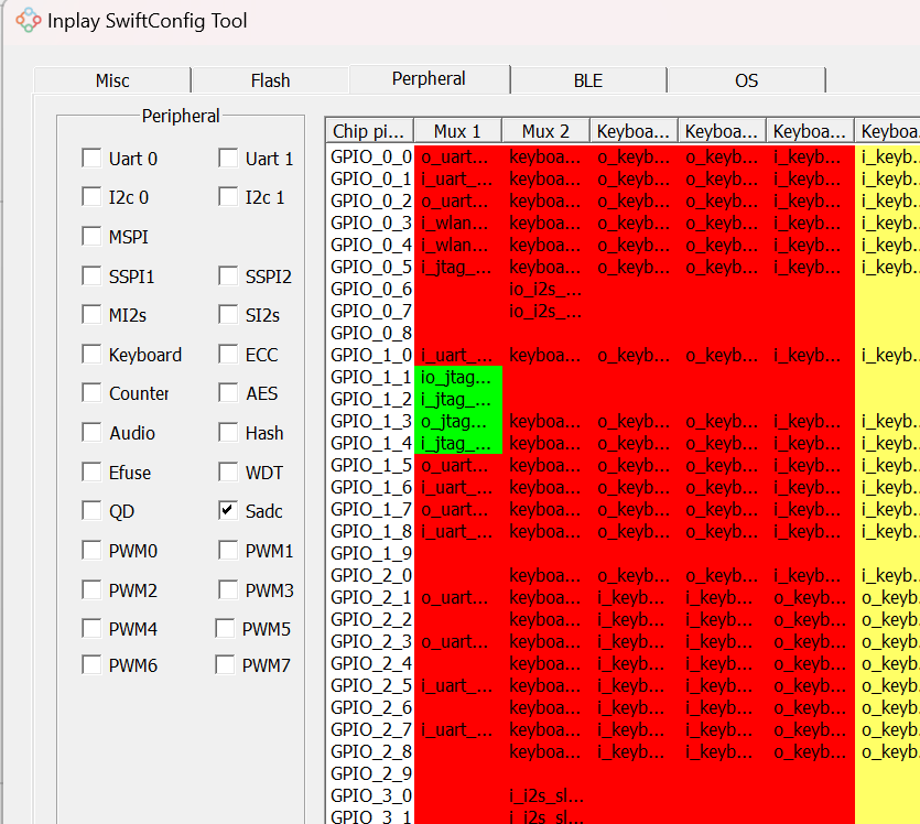
- Select “SADC” in SwiftConfig tool peripheral tab.

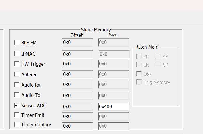
- If use auto mode, select “Sensor ADC” in Misc tab. And set SMEM size. A single sample has 2 bytes, and the minimum required size can be calculated according to the number of needed samples.
SMEM size = all channel samples * 2

Example code #
- Force Mode
Sample channel 5 in force mode:
adc_dev_t * dev = hal_adc_open();

hal_adc_force_mode_enable_ch(dev, ADC_CH5);

uint16_t buff[16];

int res = hal_adc_force_mode_start(dev, ADC_CH5, buff, 16);
- Auto Mode
Enable “ADC_CH1” and “ADC_CH2”, get 32 samples for each channel.
The sampling order is shown as follows,end after 32 cycles:
CH1 CH2 CH1 CH2 CH1 CH2 …
uint8_t buf1[32]={0};

uint8_t buf2[32]={0};

adc_dev_t * dev = hal_adc_open();

hal_adc_auto_mode_enable_ch(dev, ADC_CH1, buf1, 32);

hal_adc_auto_mode_enable_ch(dev, ADC_CH2, buf2, 32);

hal_adc_auto_mode_start(dev,32, osWaitForever);
Convert data #
Convert raw data to voltage and temperature.
- Use “hal_adc_sample_convert” to covert raw data to voltage for channel0 ~ channel 12.
- Use “hal_adc_vbat_sample_convert” for channel 14.
- Use hal_adc_temp_sample_convert" for channel 15.
These API use calibration data for coverting.