InPlay Find My SDK Guide #
Overview #
The IN610 Find My SDK is compliant with the most recent versions of both Apple’s Find My Network Accessory Specification and Google’s Find My Device Network Accessory Specification. This guide provides detailed instructions for configuring, compiling, and installing the IN610 Find My SDK to implement an IN610-based Find My Network Accessory. A typical hardware block diagram for a Find My accessory is as below:
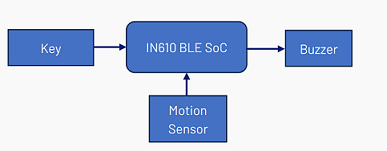
The accessory’s key components consist of the IN610 Bluetooth Low Energy (BLE) System-on-Chip (SoC), a key, a buzzer, and a motion sensor. The key acts as an input for one of the GPIOs on the IN610 BLE SoC, facilitating crucial user interactions such as restoring factory settings and turning the device on or off. The buzzer serves to emit sounds to aid in locating items, and when combined with the motion sensor, it can trigger an alarm to prevent unwanted tracking.
The SDK includes all essential hardware drivers and offers easy customization to meet your specific product needs.
Required tools #
Before using the Find My SDK, users must install the necessary tools.
Compiler and build tools #
The SDK supports both Keil and GCC. Users can build their applications using either of tools.
Keil #
If Keil is used to build the project, below tools should be installed:
| Tool | URL or the path in the SDK | Notes |
|---|---|---|
| Keil MDK | https://www.keil.com/download/product/ | It is recommended to use version 5.29 or higher of the IDE for building the project. |
| InPlayInc.DeviceFamilyPack.1.0.6.pack | in-dev/tools | Included in the SDK. Integrate IN610 support into Keil. |
GCC #
Users can also build the project using GCC on either Windows or Linux. The required tools are ARM GCC and Make.
ARM GCC
The recommended ARM GCC toolchain is gcc-arm-none-eabi-9-2020-q2. It can be downloaded from the Downloads | 9-2020-q2-update – Arm Developer page. When installing the ARM GCC toolchain, ensure that the installation path does not contain special characters such as “(” or “)”.
GNU make utility
For Windows, download the Make utility from Make for Windows and install it on your PC. If you’re using Ubuntu, install Make using the following commands:
sudo apt-get update
sudo apt-get install build-essential
After installing Make on Windows or Ubuntu, ensure you add its path to the PATH environment variable.
Image and token programming tools #
Once users successfully build the project, they can download the application image to the IN610 using either the J-Link or UART interface. These are required tools:
| Tool | URL or path in the SDK | Notes |
|---|---|---|
| SEGGER J-Link | https://www.segger.com/downloads/jlink/ | Version 7.62 or higher is recommended. |
| InPlayToolsSetup.exe | in-dev/tools | Included in the SDK. Add IN610 support for J-Flash |
The Windows application “inplay_programmer” included in the SDK (in-dev/tools/in_prog) can be used to download the application image by using UART.
The “in610_fmna_program” shown in below table is used to load the Apple token to IN610 either using J-Link or UART.
| Tool | URL or path in the SDK | Notes |
|---|---|---|
| Python 3.x | https://www.python.org/downloads/ | The In610_fmna_program utilizes a Python script to upload the Apple Find My token to the internal flash memory of the IN610. |
| in610_fmna_program | in-dev/proj/proj_ble_find_my/tools | Included in the SDK. A toolset designed for loading the Apple Find My token to the internal flash memory of the IN610. |
Source code and software architecture #
The source code for the Find My project is located in the in-dev/proj/proj_ble_find_my directory:
- build
- gcc: GCC build directory
- mdk: Keil MDK project file: proj_ble_lp.uvprojx
- inc: in_config.h is platform configuration file, fm_config.h is the Find My SDK configuration file.
- boards: Specific board configuration files
- lib: Apple and Google Find My libraries
- src
- app: Application layer, key operation definitions, storage, power on/off etc.
- bsp: Board Support Package, some necessary device drivers
- fmna: Apple Find My Network Accessory Specification related code
- nearby: Google Find My Device Network Accessory Specification related code
- utils
- tools
- in610_fmna_program: Tool to load Apple’s token to IN610 chip
- UARP: Apple’s UARP tools
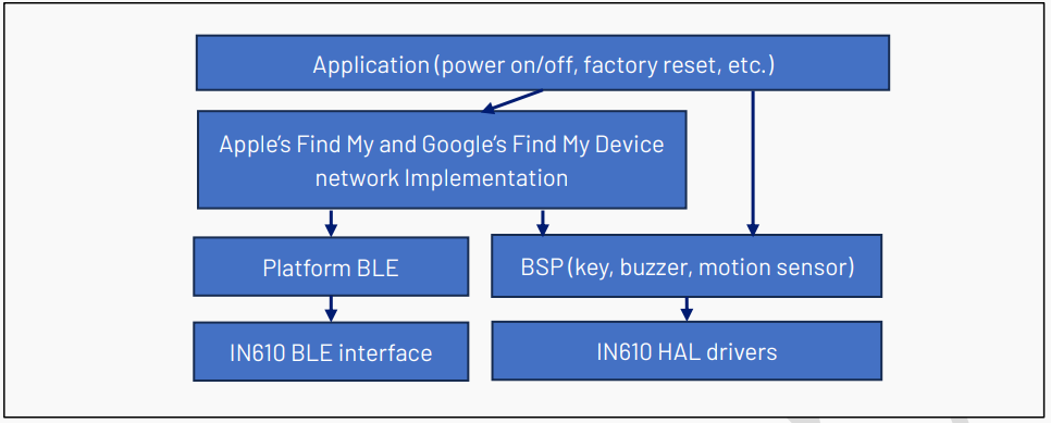
The architecture of the IN610 Find My software is illustrated as below:
Software configuration #
The configuration options for the IN610 Find My SDK are specified in the file “in-dev/proj/proj_ble_find_my/inc/fm_config.h”. This file includes a file named “fm_models.h”, which includes some hardware related macros. At the beginning of the file “fm_models.h”, a macro prefixed with “USE_” is defined to specify the target board. By default, the macro USE_DK is defined for InPlay’s IN610DK board:
#define USE_DK //DK board, B0-07102021
If you want to adapt the SDK to a custom hardware platform, you need to define a new macro, such as USE_CUSTOMER_BOARD, and provide a corresponding platform configuration file, such as “in_config_customer.h”, in the boards directory.
32k clock source #
The 32 kHz clock is a low-frequency clock used by AONPD logic. The clock source can be selected between the internal 32k RC clock and the RTC 32k clock generated by an external RTC crystal connected to the device pins RTC_XO_N and RTC_XO_P. The clock source must be configured correctly in software. If the software chooses the RTC 32 kHz clock but no external RTC crystal is present, the chip will not function.
External 32k RTC clock is the default configuration, if no external RTC crystal is connected, define the following macro to use the internal RC clock:
#define USE_32K_RC
Using the internal 32 kHz RC clock increases power consumption when the device is in BLE connection state.
BSP configuration #
The SDK’s Board Support Package (BSP) includes device drivers for key inputs, buzzer, and motion sensor functionalities. These drivers’ source code can be found in the “bsp” directory.
Key driver #
The bsp_gpio_key.c file acts as the key driver, enabling features like single press, double press, and long press etc. To enable the GPIO key driver, set the macro USE_GPIO_KEY to 1 in the fm_config.h file. The key can be connected to any available GPIO pin, and the desired GPIO can be specified using the macro defined in fm_models.h:
#define GPIO_KEY_PORT 0  // The GPIO port to which the key is connected.
#define GPIO_KEY_PIN 0    // The pin of the GPIO port that connects to the key.
#define GPIO_KEY_ACTIVE 1  // The active level of the GPIO key input.
Note: The GPIO key input should always be active at a high level. In DK board, S3 is used as the GPIO Key, which is connected to GPIO_0_0.
Buzzer driver #
The bsp_buzzer.c file serves as the buzzer driver, utilizing PWM waveforms to drive a buzzer.
Buzzers are classified into two types: magnetic buzzers and piezo buzzers. Magnetic buzzers produce sound by passing current through a coil, generating a magnetic field that moves a diaphragm to create sound waves. Piezo buzzers operate using the piezoelectric effect, where an alternating current causes a piezoelectric material to expand and contract, producing sound vibrations.
To generate a sound both magnetic buzzers and piezo buzzers require a PWM signal. The frequency of this PWM signal corresponds to the pitch of the note you want to play. Magnetic buzzers draw more current than piezo buzzers due to their fundamental design and operating principles. It is recommended to use piezo buzzers.
The IN610 features three GPIOs that support PWM:
| GPIO | Port Number | Pin Number | PWM ID |
|---|---|---|---|
| GPIO_0_2 | 0 | 2 | PWM2_ID |
| GPIO_1_7 | 1 | 7 | PWM3_ID |
| GPIO_1_8 | 1 | 8 | PWM4_ID |
Users can select which GPIO to use for PWM by configuring the corresponding macro in fm_model.h:
#define BUZZER_PWM_ID PWM2_ID //PWM id corresponding to the GPIO
For magnetic buzzers, users can configure the active level of the PWM using the following macro. The active level defines the state in which the PWM signal enables a higher current to flow through the coil:
#define BUZZER_ACTIVE_LEVEL 1
The buzzer driver allows users to customize sounds by defining buzzer sequences for various states of the Find My accessory device. Each entry in the sequence can specify how long the buzzer remains active, how long it stays inactive, and the PWM frequency during its active state. In the SDK, the following buzzer sequences are available and defined in “app_buzzer.c”:
| Buzzer sequence variable | When to be used |
|---|---|
| g_power_on_seq | The Find My accessory is powered on |
| g_power_off_seq | The Find My accessory is powered off |
| g_play_sound_seq | Played when playing sound through App, or unwanted tracking with motion detected |
| g_reset_seq | Factory reset successfully |
| g_unpair_seq | Unpaired successfully |
| g_paired_seq | Paired successfully |
Examples of buzzer sequence definitions are available in the app_buzzer.c file. One such example is the power-on sequence, which users can configure to play sounds when the device is powered on:
buzzer_seq_t g_power_on_seq = {
    .evt = g_power_on_evts,
    .repeat_count = 1,
    .seq_len = 3,
};
The g_power_on_seq buzzer sequence consists of three entries (defined by seq_len), each specifying its on duration (in 10 ms), off duration, and PWM frequency (in Hz). The repeat count is set to 1, meaning the entire sequence (comprising the three entries) will play once.
Users can call the bsp_buzzer_start_seq function to play a buzzer sequence, as shown in the following example:
bsp_buzzer_start_seq(&g_power_on_seq).
Motion sensor driver #
The “bsp_acc.c” is the motion sensor driver. Currently, the SDK supports only the LIS2DH12 as the motion sensor. The driver allows users to specify the IN610 I2C interface in use, along with one GPIO pin that can receive interrupts from the motion sensor.
The bsp_acc.c file serves as the motion sensor driver. Currently, the SDK supports only the LIS2DH12 motion sensor. The driver allows users to configure the IN610 I2C interface and specify the GPIO pin for receiving interrupts from the motion sensor.
The IN610 offers two options for the I2C interface, as outlined in below table:
| I2C ID | SCL SDA |
|---|---|
| I2C0_ID | GPIO_0_0 |
| I2C1_ID | GPIO_4_0 |
Users can select the desired interface by setting the I2C_BUS macro in fm_models.h as follows:
#define I2C_BUS I2C0_ID // Select I2C0 for the interface
The I2C address of the LIS2DH12 is determined by its SA0 pin state. If the SA0 pin is high (internally pulled-up by default), the address is 0x19. Configure this address using the I2C_ADDR macro:
#define I2C_ADDR 0x19 // I2C address of the motion sensor chip
The LIS2DH12 motion sensor generates interrupts via its INT1 and INT2 pins. The SDK uses the INT2 pin for the interrupt source for the IN610 device. When the sensor is stationary, the INT2 pin outputs a high signal. Upon detecting motion, the pin transitions to low. When returning to a stationary state, it remains low for a brief period before returning to high. Users can specify the GPIO pin on the IN610 device connected to the INT2 pin using the INT2_PORT and INT2_PIN macros in fm_models.h, as shown below:
#define INT2_PORT 2  //The port of the 2nd GPIO which can receiver interrupt from the motion sensor.
#define INT2_PIN  8 // The pin of the 2nd GPIO which can receiver interrupt from the motion sensor.
Battery driver #
The “bsp_battery.c” file functions as the battery driver for monitoring the battery voltage of the Find My accessory device. If the battery directly supplies power to the IN610, the internal ADC channel (ADC_CH14) can be used to measure the supply voltage directly. If the battery does not directly supply power to the IN610, external ADC channels of the IN610 (ADC_CH0 is recommended) must be utilized to measure the battery level. It is important to note that for external ADC channels, the input signal range must remain within [0, 2.0V]. Users are advised to implement a suitable voltage divider to ensure that the input signal range is between [50 mV, 1950 mV] for optimal linearity.
The driver enables users to define battery levels as “Full,” “Medium,” “Low,” and “Critical Low” based on the measured battery voltage (in millivolts, mV). These levels can be customized by modifying an array in the bsp_battery.c file, which maps specific voltage ranges to corresponding battery levels.
For rechargeable batteries, two threshold sets must be configured:
- g_vbat_thr in the bsp_battery.c file for batteries not in a charging state.
- g_vbat_chrg_thr for batteries in a charging state.
For non-rechargeable batteries, thresholds can be defined using g_vbat_thr.
The SDK provides example thresholds for reference. For a non-rechargeable battery, the provided examples indicate the following:
- A voltage of 2810 mV or higher corresponds to “Full.”
- A voltage between 2650 mV and 2810 mV corresponds to “Medium.”
- A voltage between 2513 mV and 2650 mV corresponds to “Low.”
- A voltage below 2513 mV corresponds to “Critical Low.”
Users can adjust the values to align with the specific characteristics of their battery.
The following macros can be defined in fm_models.h for configuring the battery driver:
#define USE_CHARGER // Define this macro if a rechargeable battery is used
#define BATT_TYPE 2  // Indicates a rechargeable battery; this value is used to initialize Find My libraries
#define BAT_VOL_ADC_CH ADC_CH0  // Specifies the ADC channel used to sample battery voltage
#define BAT_VOLTAGE_DIV ((1.2+1.5)/1.2)  // Battery voltage divider configuration
#define BAT_STABLE_DELAY (200000) // Delay (in microseconds) for battery voltage stabilization after reset; set to 0 for ADC_CH0. For mixed-signal pins, additional delay may be needed due to pull-up resistors.
If a GPIO pin is connected to the charger for detecting the charging state, it can be defined as follows:
#define GPIO_CHARG_DET 2,5
Note: If GPIO_CHARG_DET is not defined, the software cannot detect the charging state. Consequently, the g_vbat_chrg_thr parameter will not be used.
To ensure the tracker powers off automatically when the battery is low, define the following macro in bsp_battery.h to set the power-off voltage for the rechargeable battery:
#define BAT_POWER_OFF_VOL 3300 // Power off battery voltage in millivolts (mV)
If a load switch is used to control the battery voltage sampling, you can define the GPIO pin to manage the load switch as follows:
#define GPIO_BAT_ADC_EN 1, 8  // Define GPIO to enable load switch
#define ADC_EN_ACTIVE 1  // Define active level of the GPIO
Boot Pin #
The boot pin is utilized to signal the boot ROM of the IN610 that a firmware image or data (like Apple token) needs to be downloaded to the flash memory. In the SDK, the default boot pin is GPIO_1_6. If the boot pin is low during the transition of the chip from disabled to enabled (when the CHIP_EN pin goes from low to high), the chip will remain in the boot ROM, awaiting commands from any UART interface to initiate the firmware download. Users can also connect a J-Link to the IN610 in this state.
SDK configuration #
Several SDK configuration macros are defined in the fm_config.h file, as detailed in the following sub-sections.
Debug option #
The Keil project includes two targets: tracker (release version) and tracker_d (debug version). The differences between these targets are outlined in below table:
| Target | Linked libraries | FMND_DEBUG defined? | Description |
|---|---|---|---|
| tracker | fmna_lib.lib, nearby_lib.lib | No | Debug messages will not be output via UART. The “Debug Control Point” outlined in the “Find My Network Accessory Specification” is not activated. Less flash memory is needed. |
| tracker_d | fmna_lib_d.lib, nearby_lib_d.lib | Yes | Debug messages will be output via UART. The “Debug Control Point” outlined in the “Find My Network Accessory Specification” is activated. More flash memory is needed. |
Note:
- The default debug UART interface is UART1 in the IN610 device, GPIO_2_1 as TXD and GPIO_2_7 as RXD. And the baud rate is 921600.
- If non-debug version libraries (libraries without “_d” suffix) are used, RAM log are not supported.
Supported protocol #
The SDK supports both the Apple Find My and Google Find My Device protocols. The tracker can be configured to support either one or both.
- If the tracker is configured for one protocol, it can only join the corresponding predefined network.
- If configured for both, the end user can choose whether the tracker joins the Apple or Google network during a factory reset or the first-time power-on.
To support the Apple Find My protocol, define the following macro in fm_config.h:
#define USE_APPLE_TRACKER
To support the Google Find My Device protocol, define the following macro:
#define USE_GOOGLE_TRACKER
Watchdog #
Set the following macro to enable the IN610’s AON Watchdog. It is recommended to keep this enabled. To disable the WDT, set the macro to 0:
#define USE_WDT 1
RAM log #
Set the following macro to “1” to enable log printing to RAM. You can dump the logs using the InPlayOTA application. This option should be disabled for release versions:
#define USE_RAM_LOG 1
DFT (Design for Test) BLE service #
DFT service is a BLE service used to write SN, token or dump log. If users don’t need these features, users should set these options to “0”.
#define USE_DFT_SVC 1 // If set to "1", a BLE service will be included for testing purposes. For details, refer to app_dft.c.
#define USE_DFT_ADV 0 // If set to "1", an additional BLE advertisement for testing purposes will be enabled for 1 minute when entering pairing state.
Google FMDN and Apple FMNA configuration #
The configuration options for Google FMDN can be set using the nearby_cfg_t structure when calling nearby_init to initialize the Nearby library. Refer to nearby_user.h for the structure definition.
Similarly, the configuration options for Apple FMNA can be set using the fmna_cfg_t structure when calling fmna_init to initialize the FMNA library. Refer to fmna_user.h for the structure definition.
In app_power_state.c, the initialization is implemented as follows:
- Google FMDN is initialized with: nearby_init(&nearby_cfg, reset_reason, &g_app_cfg.fmdn_data);
- Apple Find My Network is initialized with: fmna_init(&fmna_cfg, &nv_data);
The configuration options are defined as global variables (fmna_cfg and nearby_cfg). Certain members of these structures are initialized using macros.
Model setup configuration #
For the Google tracker, it is essential to correctly configure the model ID and anti-spoof private key; For the Apple tracker, the product data should be set correctly. They are defined as macros in “in-dev/proj/proj_ble_find_my/inc/fm_private.h”.
Note: By default, these essential macros are set to invalid values. If they are not modified, the tracker will not work.
- MODEL_ID: Model ID distributed by Google
- ANTI_SPOOF_PRIV_KEY: Anti-Spoofing Private Key distributed by Google
Refer to Fast Pair|Google for Developers to know how to register a model with Google.
The Anti-Spoofing Private Key distributed by Google is BASE64 encoded, it should be converted to hexadecimal format, some online tools can be used to do this:
https://base64.guru/converter/decode/hex
For example, if the Base64-encoded private key string is: “AQIDBAUGBwgJCgsMDQ4PEBESExQVFhcYGRobHB0eHyA=”
Convert it to hexadecimal:
“0102030405060708090a0b0c0d0e0f101112131415161718191a1b1c1d1e1f20”
Then, define the private key in fm_private.h as follows:
#define ANTI_SPOOF_PRIV_KEY \
    0x01, 0x02, 0x03, 0x04, 0x05, 0x06, 0x07, 0x08, \
    0x09, 0x0a, 0x0b, 0x0c, 0x0d, 0x0e, 0x0f, 0x10, \
    0x11, 0x12, 0x13, 0x14, 0x15, 0x16, 0x17, 0x18, \
    0x19, 0x1a, 0x1b, 0x1c, 0x1d, 0x1e, 0x1f, 0x20,
For the Apple tracker, the product data must be set accurately which is also defined in “fm_private.h” as FMNA_PRODUCT_DATA.
Certain common options must be configured for both Apple and Google, including firmware version number, manufacturer name, model name, capability, category, and battery type. Definitions for some macros related to capability, category, and battery type can be found in “fm_constants.h”.
RF related configuration #
Certain RF-related configurations must be adjusted to align with the hardware setup. For the IN610 chip, the gain code parameter is used to configure the RF Tx power. Typically, the following values are used:
- gain_code = 0x18: Tx power set to 0 dBm
- gain_code = 0x78: Tx power set to 4 dBm
However, these values may vary depending on hardware specifics, such as the RF matching network.
In the IN610 SDK, the Tx power for each advertisement can be configured independently. During a connection, the Tx power used matches that of the corresponding advertisement.
For Apple Find My, the Tx power must be set to higher than 4 dBm. The relevant settings are members of the fmna_cfg_t structure:
- tx_pwr: Represents the Tx Power Level characteristic of the Tx Power Service for FMNA and should reflect the Bluetooth LE TRP (Total Radiated Power).
- tx_gain_code: Configures the Tx power setting of the chip for FMNA advertisements.
For Google Find My, two types of advertisements are used: Fast Pair and FMDN. Fast Pair advertisements are active during pairing and FMDN advertisements are used after pairing.
The configurations are members of the nearby_cfg_t structure:
- fp_calibrated_adv_tx_pwr: The calibrated Fast Pair Tx power at 0m distance, measured in dBm. Refer to Fast Pair Materials and Technical Notes | Google for Developers on the Google Developers site.
- fp_tx_gain_code: Configures the Tx power setting for Fast Pair advertisements and must be lower than fmdn_tx_gain_code.
- fmdn_tx_gain_code: Configures the Tx power setting for FMDN advertisements.
Apple Find My Serial Number interface #
The serial number for Apple Find My is retrieved by the Apple Find My library using the function fmna_plat_get_serial_number in the file fmna_platform.c. By default, the serial number is generated from the chip UUID. However, if USE_NV_SN is set to “1”, the serial number can be read from flash memory instead.
Function interface #
Functions declared in “fmna_platform.h” and “fmna_platform_uarp.h” are called by fmna lib. Functions defined in “nearby_platform_os.c” are called by nearby lib. Functions declared in “fmna_user.h” and “nearby_user.h” are APIs called by user application, which are implemented in fmna lib and nearby lib.
Flash layout #
The flash address 0x0 is mapped to 0x00300000 in the CPU addressing space. Below table provides detailed information about the flash layout.
512KB Flash: #
| Address range | Description |
|---|---|
| 0x0 ~ 0x4000 | Boot options and Boot RAM |
| 0x4000~0x40000 | Application bank A |
| 0x40000~0x7B000 | Application bank B |
| 0x7B000~0x7E000 | Pair information and keys |
| 0x7E000~0x7F000 | Apple software authentication token |
| 0x7F000~0x80000 | Reserved, can be used to store SN, etc. |
1MB Flash: #
| Address range | Description |
|---|---|
| 0x0 ~ 0x4000 | Boot options and Boot RAM |
| 0x4000~0x80000 | Application bank A |
| 0x80000~0xFB000 | Application bank B |
| 0xFB000~0xFE000 | Pair information and keys |
| 0xFE000~0xFF000 | Apple software authentication token |
| 0xFF000~0x100000 | Reserved, can be used to store SN, etc. |
Note: The SDK supports firmware upgrades using A/B banks. At any given time, the application program is stored in either Application Bank A or Application Bank B. Keil can only program firmware to Bank A. If the firmware is upgraded to Bank B, the sector at address 0x3000 must be erased before running a program loaded with Keil.
UI customization #
A Find My Accessory typically supports several operations, including enabling or disabling the Find My Network, performing a factory reset, and reading the serial number. This section offers guidance on how to customize these operations within the SDK.
Find My Network disable/enable #
The enable/disable function for Find My Network has been implemented as a power on/off feature in the SDK. When in power off state, the chip will enter deep sleep mode, which is a state where the system consumes minimal power. The user interface for power on/off is defined in app_key.c. To trigger power on/off operations, call the function app_power_set_state.
Note: By default, a long press of the button for 3 seconds will initiate the power-on operation. To trigger the power-off operation, quickly press the button three times, then long press it for 5 seconds immediately afterward.
Factory Reset #
In app_key.c, you can initiate a factory reset by calling the function do_factory_reset.
Note: By default, quickly press the button 5 times will trigger factory reset.
Read Serial Number #
In app_key.c, you can enable reading the serial number by calling the function enable_serial_read.
Note: By default, a double press of the button activates the serial number read mode.
Multiple BLE applications coexist #
When multiple BLE applications are running simultaneously, they typically exhibit the following characteristics:
- Each application has its own type of advertising packets.
- Each application performs different actions during connection and disconnection.
- Each application defines its own unique GATT services.
Multiple BLE applications can run simultaneously with the SDK, this is achieved through the following steps:
- When establishing a connection, map the connection index to the corresponding BLE application based on the type of advertising packet associated with the connection.
- Subsequently, in the callback function for the same connection index, invoke the callback function of the corresponding BLE application for processing.
This feature is implemented in “app_ble.c”, user can register a BLE application with “app_ble_register” function. Each BLE application is defined with a “app_ble_t” type structure which is composed by a few BLE callback functions. BLE callback functions not implemented for the application should be filled with “NULL”. The “check_adv_actv” callback function is used to check if an activity index is related to the application, it should return 1 if this is true.
Build the project and load the program to the flash #
Build the project with Keil #
The Keil project file is “in-dev/proj/proj_ble_find_my/build/mdk/proj_ble_lp.uvprojx”, open it with Keil and then select the appropriate target (refer to Debug option). If the build is successful, a file named “ble_find_my.bin” will be generated in the “in-dev/proj/proj_ble_find_my/build/mdk” directory. That file is the firmware image users need to load it to the IN610’s flash.
Build the project with GCC #
Follow below steps to build the project.
- Unzip InPlay SDK to any directory.
- If you’re using Ubuntu, open the file in-dev/proj/common/gcc/linux.mk and set the GNU_INSTALL_ROOT to the path of your ARM GCC installation. For Windows users, modify the in-dev/proj/common/gcc/windows.mk file instead. Note that in windows.mk, you should use forward slashes “/” as the path separator, rather than backslashes “\”.
- For Ubuntu users, navigate to the “in-dev/proj/proj_ble_find_my/build/gcc directory and execute the following command in your terminal:
make -j4
This will build a release version by default (No logs will output). If you want to build a debug version, run below command:
make -j4 EN_DEBUG=1
Run below command to clean the project, then you can rebuild the project:
make clean
If the build is successful, a file named “ble_find_my.bin” will be generated in the “in-dev/proj/proj_ble_find_my/build/gcc” directory. That file is the firmware image users need to load it to the IN610’s flash.
Note: If you build the project on Windows, PowerShell or Command Prompt are not supported. It is recommended to install Git for Windows and execute the “make” command in “Git Bash” shell.
Load the image to IN610L flash #
The boot pin signals the boot ROM of the IN610 to initiate firmware image download to the flash memory. If the device is already programmed, its state may be uncertain (e.g., it could be in deep sleep or active mode). In such cases, the boot pin assists in preparing the device for image loading. Follow these steps to load an image to the flash:
- Connect the boot pin to ground (not required if the device has never been programmed).
- Perform a power cycle on the device or toggle the CHIP_EN pin from low to high.
- Use the preferred tool to load the image to the device’s flash memory.
Load the image with J-Link #
Flash Programming with Keil
Keil supports flash programming via J-Link. For configuration details on the programming utility in Keil for IN610L, refer to Quick Start | InPlay Doc. After building the project, users can use Keil to load the image into the device’s flash memory.
Flash Programming without Keil
If Keil is unavailable, users can load the firmware binary (e.g., ble_find_my.bin) using J-Link. Refer to IN610 J-Flash Download Guide.
Load the image with UART #
If J-Link is unavailable, users can load the firmware binary (e.g., ble_find_my.bin) using “InPlay Programmer” tool through UART. Refer to InPlay Programmer Guide.
Run the program #
The default debug UART port is UART1, using GPIO_2_1 for Tx and GPIO_2_7 for Rx, with a baud rate of 921600. If the program is a debug version and executes successfully, logs will be output through the UART port.
Load Software Authentication Token / UUID #
Every Apple Find My accessory must have a unique token issued by Apple Inc. This token will be utilized once during the pairing of the accessory, and a new token will be provided during the pairing process, which should then be stored in non-volatile memory. This section explains the process of loading software authentication tokens on Windows.
Token item format #
A token item in excel file is as:
 A token item has an UUID and a base64-encoded token value.
Run the script #
In610_fmna_program.py is the python script to load the token. It can support both J-Link and UART.
Load token with J-Link #
Before running the script, follow JFlash Programming | InPlay Doc to make sure you can program IN610 flash with J-Link. You should also add the directory path that contains “J-Link.exe” to the PATH environment variable. You can refer Add to the PATH on Windows 10 and Windows 11 | Architect Ryan to know how to do this.
To load the token, connect J-Link to IN610 chip and run the script as below:
- 512KB flash
python ./in610_fmna_program.py --mfi-token [token-UUID] [token-base64]
- 1MB flash
python ./in610_fmna_program.py --mfi-token [token-UUID] [token-base64] --flash 1
where token-UUID represents the UUID of the token and token-base64 is the base64-encoded token value.
This is an example:
- 512KB flash
python ./in610_fmna_program.py --mfi-token 9748f95c-1678-4c73-9a77-15ed5c5473c9 MYG9ME0CAQECAQEERTBDAh8fGFpEniKAqaM+PoxcZc95fXq1p71bCC6KXoeB+89TAiAG8hHm33V/peyFz7f4Cqe+TmuoqW8qnVW+Z1nLXqD/gjBsAgECAgEBBGQxYjAJAgFmAgEBBAECMBACAWUCAQEECDfGbPyNAQAAMBECAgDKAgEBBAgAAAAAAAAACDAWAgIAyQIBAQQNMjYyOTgzLTczMDExMTAYAgFnAgEBBBB/5DXuqMpN+JOWBM/IEzc+
- 1MB flash
python ./in610_fmna_program.py --mfi-token 9748f95c-1678-4c73-9a77-15ed5c5473c9 MYG9ME0CAQECAQEERTBDAh8fGFpEniKAqaM+PoxcZc95fXq1p71bCC6KXoeB+89TAiAG8hHm33V/peyFz7f4Cqe+TmuoqW8qnVW+Z1nLXqD/gjBsAgECAgEBBGQxYjAJAgFmAgEBBAECMBACAWUCAQEECDfGbPyNAQAAMBECAgDKAgEBBAgAAAAAAAAACDAWAgIAyQIBAQQNMjYyOTgzLTczMDExMTAYAgFnAgEBBBB/5DXuqMpN+JOWBM/IEzc+ --flash 1
Load token with UART #
Before running the script, check section Load the image to IN610L flash to ensure the chip is in Boot ROM mode and ready to download an image via UART. To load the token, connect your PC to any UART port on the IN610 chip. Then, include the “–com” parameter to specify the COM port number used for the connection. This is an example:
python ./in610_fmna_program.py --com 89 --mfi-token 9748f95c-1678-4c73-9a77-15ed5c5473c9 MYG9ME0CAQECAQEERTBDAh8fGFpEniKAqaM+PoxcZc95fXq1p71bCC6KXoeB+89TAiAG8hHm33V/peyFz7f4Cqe+TmuoqW8qnVW+Z1nLXqD/gjBsAgECAgEBBGQxYjAJAgFmAgEBBAECMBACAWUCAQEECDfGbPyNAQAAMBECAgDKAgEBBAgAAAAAAAAACDAWAgIAyQIBAQQNMjYyOTgzLTczMDExMTAYAgFnAgEBBBB/5DXuqMpN+JOWBM/IEzc+
Generate UARP file #
UARP is Apple’s Unified Accessory Restore Protocol. IN610 Find My SDK support firmware update compliant with UARP. Related files for this section are in proj_ble_find_my/tools/UARP directory.
Generate the input bin to “mfigr2” tool #
Note: Below steps can be done in Windows or MacOS
The .uarp file is an upgrade package for UARP. To generate .uarp file, preprocessing is required on the bin file that is generated from compilation:
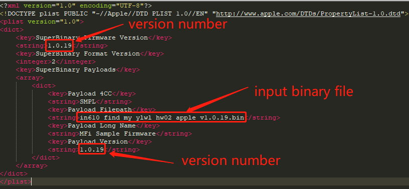
Copy the generated binary file (ble_find_my.bin) to the same directory as script “generate_bin.py”, and rename it to “input.bin”, then double click on the “generate_bin.py”, a file named “output_hashed.bin” will be generated, and it will be used as input file in following steps. Copy output_hashed.bin to the same directory as MyUARPSuperBinary.plist and rename it as you like. Then fill version number and the input binary file name (renamed output_hashed.bin) in “MyUARPSuperBinary.plist”.
Use “mfigr2” to generate .uarp file #
Note: below steps can only be done in MacOS
Run mfigr2 in shell to generate the UARP file (mfigr2 can only be executed in MacOS):
./mfigr2 superbinary compose metaDataFilepath=UARPMFIMetaDataTable2.plist plistFilepath=MyUARPSuperBinary.plist payloadsFilepath=. superBinaryFilepath=MyUARPSuperBinary.uarp
If the command executes successfully, a file named “MyUARPSuperBinary.uarp” will be generated, this is the final .uarp file, you can rename it as you like.
Upgrade the Find My Accessory #
Install the FMCA Application #
Find My Certification Assistant requires a device running iOS or iPadOS 14.5 or later. Use your iPhone to open link Find My Certification Asst. on the App Store on the App Store. Clicking on the link will open the App Store application, where you can proceed to install the app.
Install Find My Network Configuration Profile #
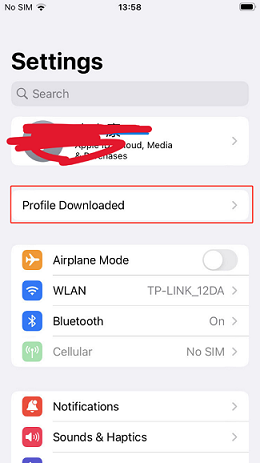
Testing accessory firmware updates requires the installation of the Find My Network Configuration Profile. Extract the contents of the file “FMCA Configuration Profile Jan 2024.zip” to obtain a file named “Find_My_Certification_Configuration.mobileconfig”. Transfer this file to your iPhone using AirDrop (it is recommended to use AirDrop). Next, navigate to the “Settings” app on your iPhone, where you will find the “Profile Downloaded” button.
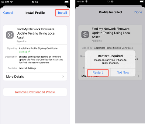
Click on the button and continue with the profile installation:
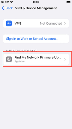
After restarting your iPhone, you can verify its installation by checking in “Settings” -> “General” -> “VPN & Device Management”.
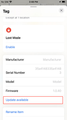
Update the firmware #
A UARP firmware file is denoted as “xxxx.uarp.” Begin by transferring the file to your iPhone. Prior to conducting the update, pair the Find My Accessory with your iPhone. Next, open the “FMCA” app, sign in using your Apple ID (which should be your company account), and locate your device under “My Items”. Select your device, then tap the “Firmware Settings” button. Choose the option to “Select a File…” and pick the .uarp file. Ensure you do not leave the page, and proceed to open the “Find My” app. Select the device you wish to upgrade; if the .uarp file is recognized correctly, the “Update Available” button will be displayed as shown below. Then tap the button to start upgrading. If you can’t see “Update Available” button, try to restart your iPhone and repeat the above steps.