InPlay Programmer Guide #
Introduction #
The InPlay Programmer is a graphical chip configuration and programming tool for the PC that enables developers to configure and download programs to target boards using InPlay chips via UART. Developers should refer to the chip datasheet to thoroughly understand the configuration options based on their specific application requirements.
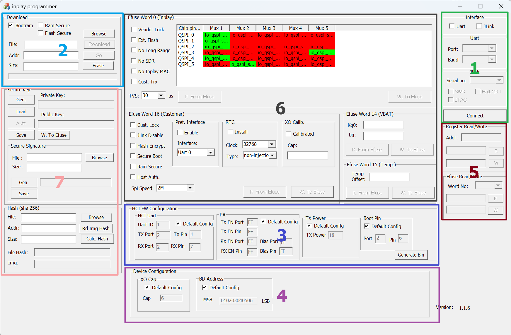
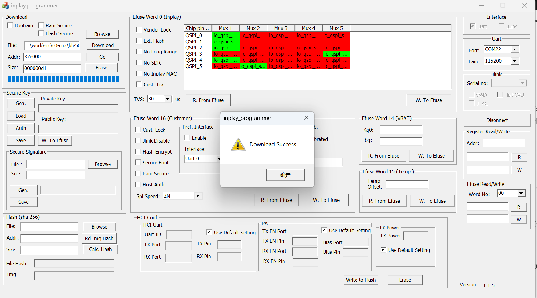
The main window of the GUI tool, as shown in Figure 1, is organized into five area:
- Data communication interface selection and configuration area
- Application download area
- HCI FW configuration area
- Device configuration area
- Register/eFuse read-write area
- Efuse configuration area
- Authentication and encryption configuration area
Note: All numbers entered in input fields are in hexadecimal format, and you do not need to include the “0x” prefix. For example, to set the address to “0x300000”, simply enter “300000”.
UART Download #
Prerequisites #
- Connect the DK board’s UART port to the PC.
- Set the chip to boot mode.
Boot Mode #
- The chip has two modes: boot mode and normal mode. In boot mode, it can be configured and programmed via UART/JLink, while in normal mode, the chip runs the program already downloaded to it.
- A GPIO pin can be configured as the boot pin in software, and the chip will check the GPIO level at power-on to determine whether to enter boot mode. In the SDK’s demo project, GPIO2_6 is set as the default boot pin.
- If the chip has no loaded program (i.e., a blank chip), it will automatically enter boot mode on power-up.
- If a program is already loaded, ground the boot pin and then power cycle or reset the chip to enter boot mode.
Connecting to the UART (Area 1) #
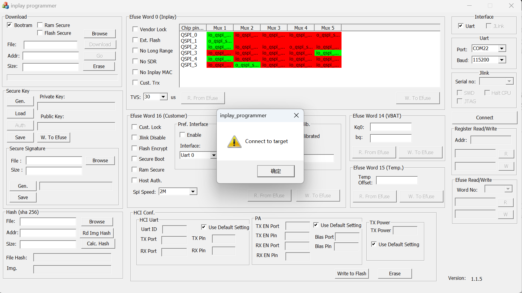
- Click on “Uart” in area 1 to automatically scan for UART ports on the PC.
- Select the DK board’s port from the dropdown list under “Port.”
- The program sets the baud rate to 115200 by default.
- Click Connect. If the connection is successful, a dialog will appear. The program will continue attempting to connect for up to five minutes. To cancel, close and reopen the program.
Program Download (Area 2) #
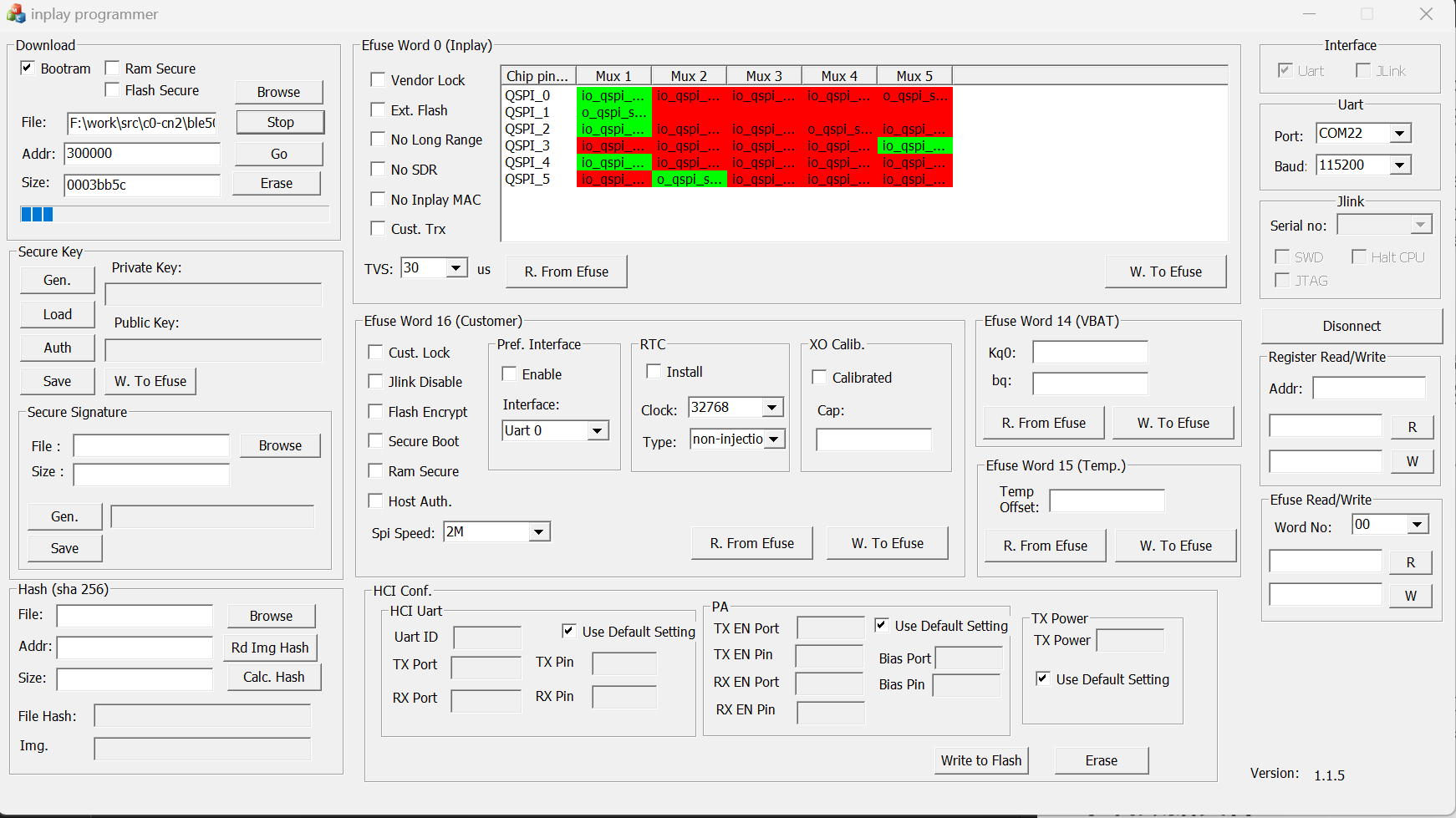
- Ensure that BootRAM is checked in area 2.
- Click Browse to select the application binary file.
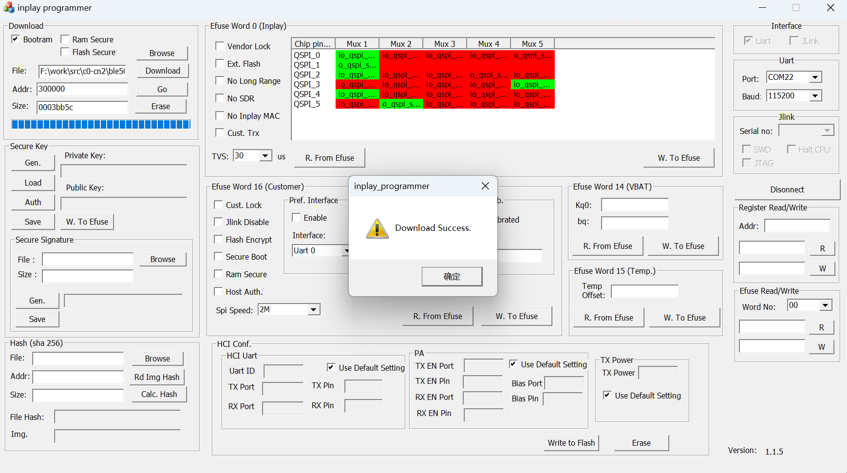
- Verify the Address is set to 0x300000. The program will automatically calculate the size; no adjustments are needed.
- Click Download. A dialog will appear upon successful download.
Data File Download (Area 2) #
Some programs may require downloading data files, such as calibration data or tokens/UUIDs, to specific locations. This step can be done after downloading the application binary file. Note: If no program has been downloaded previously, data files cannot be downloaded directly.
- Uncheck Bootram.
- Click Browse to select the binary file containing the data.
- Set the Addr as required; for example, to load data at 0x37E000, set the address to 37E000.
- Size will be set automatically, but it can be adjusted as needed.
- Click Download.
HCI Firmware Configuration (Area 3) #
This section configures the HCI Firmware, including HCI Firmware’s UART, PA, and TX Power settings.
HCI UART #
- Check “Use Default Setting” to use the default configuration. By default, UART 1 uses GPIO2_1 and GPIO2_7.
- To use a custom configuration, uncheck “Use Default Setting.”
- Set the UART ID, which can be either 0 or 1.
- Configure the TX Port and TX Pin. UART 0 allows GPIO0_2 or GPIO2_3, while UART 1 allows GPIO2_1 or GPIO1_7.
- Configure the RX Port and RX Pin. UART 0 allows GPIO1_0 or GPIO2_5, while UART 1 allows GPIO2_7 or GPIO1_8.
PA Pin #
- Check “Use Default Setting” to use the default configuration. By default, no PA Pin is set.
- To use a custom configuration, uncheck “Use Default Setting.”
- Set the TX_EN Port, TX_EN Pin, RX_EN Port, RX_EN Pin, Bias Port, and Bias Pin.
- If a pin is not to be configured, set both Port and Pin to “FF”.
TX Power #
- Check “Use Default Setting” to use the default configuration. By default, the TX Power is set to 0x18 (0dBm).
- To use a custom configuration, uncheck “Use Default Setting.”
- Set the TX Power, which ranges from 0x0 to 0x7F.
Boot Pin #
- Check “Use Default Setting” to use the default configuration. By default, the boot pin is GPIO2_6.
- To use a custom configuration, uncheck “Use Default Setting.”
- Set port.
- Set pin.
Generate Bin File #
Must click the browse button (Area 2) to select the original bin file first.
Then if you click “Download” bnutton, the configuration will be written into the flash but will not modify the original bin file. If you need to download it again, you must configure it again.
Clicking the “Generate Bin” button will create a bin file with the configured information. And it will not modify the original bin file. If download the generated bin file, don’t need to configure the HCI Firmware Configuration (Area 3). Just select all “Default Config” options.
Device Configuration (Area 4) #
This section is used to configure device-related information, which will be stored separately at address 0x37F000. Therefore, if the configuration has already been set and downloaded, there is no need to configure it again for subsequent downloads.
Note: Make sure to check “Device Config” in the SwiftConfigTool for this configuration to take effect.
XO Cap #
- Check “Use Default Setting” to use the default configuration. The default values are set in SwiftConfigTool.
- To use a custom configuration, uncheck “Use Default Setting.”
- Set the cap value, which ranges from 0x0 to 0xF.
BD Address #
- Check “Use Default Setting” to use the default configuration. The default values are set in SwiftConfigTool.
- To use a custom configuration, uncheck “Use Default Setting.”
- Set the BD address.
Troubleshooting #
DK board’s UART port not listed:
- Uncheck UART, then re-check it to rescan for UART ports.
Connection fails upon clicking Connect:
- Ensure the port is not occupied by another program.
No success dialog after clicking Connect:
- Verify the selected port is correct.
- Confirm that the chip is in boot mode.
- Disconnect all connections to the chip, such as UART and JLink connections. Then pull down boot pin and reset the chip. After that, reconnect the serial port to the chip and click “Connect.”
Download fails upon clicking Download:
- Ensure the correct binary file is selected.
- Verify Bootram is checked.
- Confirm Addr and Size settings are correct.
Data file download fails upon clicking Download:
- Verify the correct binary file is selected.
- Ensure Bootram is unchecked.
- Confirm Addr and Size settings are correct.