Counter Guide #
Introduction #
The counter block contains 4 32-bit identical counters. Each counter can be independently programmed to perform a wide range of functions including frequency measurement, event counting, interval measurement, pulse generation, delay timing and pulse width modulation.
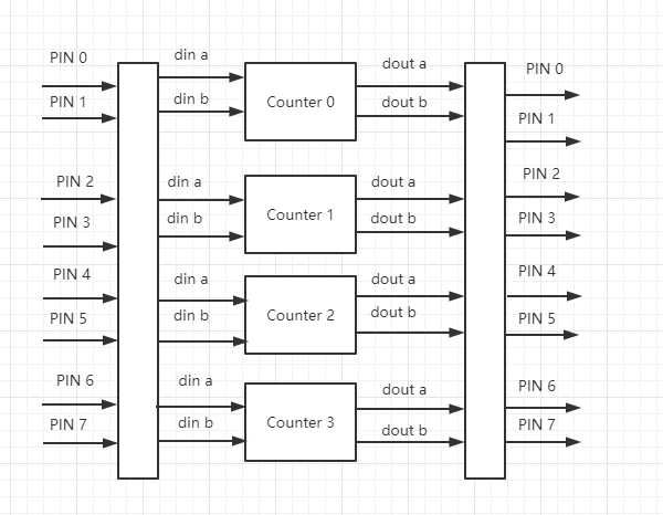
The 6XX series chips have 4 built-in counter modules, corresponding to these 8 pins (GPIO port 2). The counter module can be used to achieve functions like PWM, Timer, IrDa, and 7816.
For details, please refer to:
Hal_cnt_pwm.c

Hal_cnt_timer.c

Hal_ir.c

Hal_sync7816.c
Counter Mode #
The counter supports four modes:
- Capture Mode:
In Capture Mode, the counter captures waveforms on din A and din B. It detects falling edge and rising edge, records the timestamp into corresponding registers.
Capture Register 0: Stores the counter value at the first event trigger(falling edge or rising edge).
Capture Register 1: Stores the counter value at the second event trigger(falling edge or rising edge).
Capture Register 2: Stores the counter value at the third event trigger(falling edge or rising edge). Subsequent event triggers will overwrite Capture Registers 0, 1, and 2.
Waveform Mode: In Waveform Mode, the counter outputs signals on “Dout A” and “Dout B” based on the values stored in the target registers.
- Target Register 0: Outputs 0 when the counter reaches the specified value.
- Target Register 1: Outputs 1 when the counter reaches the specified value.
- Target Register 2: Stops output when the counter reaches the specified value.
Shift In Mode: In Shift In Mode, the counter reads signals from “Din A” and “Din B” on every clock cycle, capturing one bit at a time.
Shift Out Mode: In Shift Out Mode, the counter outputs signals to “Dout A” and “Dout B” on every clock cycle, transmitting one bit at a time.
Mode Switching: When automatic mode switching is enabled, Capture Mode and Waveform Mode can automatically switch. Similarly, Shift In Mode and Shift Out Mode can also automatically switch.
Configuration #
Each counter has two input signals: “din A” and “din B”, as well as two output signals: “dout A” and “dout B”. These internal signal can be configured to connect to external pins. Specifically, these pins are represented as PIN0 to PINI7 (GPIO21 to GPIO28) on the diagram.

Select “Counter” in config tool and select the corresponding pin according to the actual circuit.

Refer to:
int hal_cnt_internal_din_pinmux(int inner_pin, int ext_pin)

int hal_cnt_internal_dout_pinmux(int inner_pin, int ext_pin)
EXT_DIN is from PIN0~PIN7.
INNTER_DIN is internal din signal from four counters.
Interrupt #
Interrupt status. Each bit is represented as follows:
CNT_A_UPDATE 1	capture register a0 a1 a2  all updated

CNT_B_UPDATE 0x2	capture register b0 b1 b2  all updated

CNT_OVERFLOW 0x4	counter overflow  the counting will restart

CNT_SHIFTIN_COMPLETE 0x8 shift in completed

CNT_SHIFTOUT_COMPLETE 0x10	shift out completed

CNT_WAVEFORM_STOP 0x20	waveform stop, the counter has reached the value of register a2/b2

CNT_SHIFTIN_CAPTURE_END 0x40	in the automatic switching mode, capture or shift in is completed

CNT_SHIFTOUT_WAVEFORM_END 0x80 in the automatic switching mode, waveform or shift out is completed
API #
Set the callback of the interrupt. #
The callback fun will be called during the interrupt.
void hal_cnt_set_handler(cnt_dev_t *dev, CNT_ISR_FUN fun, void *arg)
Mask/unmask interrupt #
int hal_cnt_intr_unmask(cnt_dev_t* dev)

int hal_cnt_intr_mask(cnt_dev_t* dev)
Enable/Disable #
void cnt_enable(uint32_t base)

void cnt_disable(uint32_t base)
Trigger and signal source #
The counter can be set to be triggered by signal or manually.
Set the signal source and edge
void cnt_set_src_edge(uint32_t base, uint32_t src_edge)
Signal source:
#define CNT_EXT_DIN_A 1

#define CNT_EXT_DIN_B 2

#define CNT_GLOBAL_START_TRIGGER 3

#define CNT_SINGLE_START_TRIGGER 4

#define CNT_GLOBAL_STOP_TRIGGER 5

#define CNT_SINGLE_STOP_TRIGGER 6

#define CNT_INNER_DIN0 11

#define CNT_INNER_DIN1 12

#define CNT_INNER_DIN2 13

#define CNT_INNER_DIN3 14
Global trigger will trigger all four counters, single trigger will only trigger one counter.
Edge
#define CNT_RISING_EDGE 0

#define CNT_FALLING_EDGE 0x10UL

#define CNT_BOTH_EDGE 0x20UL
Signal
Start signal
#define CNT_START_SIGNLE_SHIFT 0
Stop signal
#define CNT_STOP_SIGNLE_SHIFT 8
Din 0 signal
#define CNT_DIN0_SHIFT 16
Din 1 signal
#define CNT_DIN1_SHIFT 24
Example #
Set the external DIN A as the start signal. Double edge trigger. The DIN0 signal is the external DIN A. Double edge trigger.
cnt_set_src_edge(cnt_dev->base, (CNT_EXT_DIN_A | CNT_BOTH_EDGE) << CNT_START_SIGNLE_SHIFT | (CNT_EXT_DIN_A | CNT_BOTH_EDGE) << CNT_DIN0_SHIFT);
Manual trigger #
void cnt_trigger_start (uint32_t base)

void cnt_trigger_stop (uint32_t base)
Set the internal signal #
void cnt_set_input_mux(uint32_t base, uint32_t val)
Parameter Val, bus A by default
#define CNT0_BUS_B 0x1

#define CNT1_BUS_B 0x2

#define CNT2_BUS_B 0x4

#define CNT3_BUS_B 0x8
Target control #
void cnt_set_target_ctrl (uint32_t base, uint32_t ctrl)
The behavior when the counter reaches register A2.
Keep or reset value. Reset value by default.
#define CNT_A2_KEEP_VALUE 0x1UL

#define CNT_A2_RESET_VALUE 0x0UL
Stop or restart counter. Restart by default.
#define CNT_A2_STOP_COUNTER 0x2UL

#define CNT_A2_RESTART_COUNTER 0x0UL
The behavior when the counter reaches register B2
Keep or reset value. Reset value by default.
#define CNT_B2_KEEP_VALUE 0x4UL

#define CNT_B2_RESET_VALUE 0x0UL
Stop or restart counter. Restart by default.
#define CNT_B2_STOP_COUNTER 0x8UL

#define CNT_B2_RESTART_COUNTER 0x0UL
Set the value when resetting
#define CNT_DOUT_A_RESET_VALUE_SHIFT 4

#define CNT_DOUT_B_RESET_VALUE_SHIFT 5
Example: #
B2 is to hold and stop counter, while A2 resets value and stops counter. The reset values are both set to 0.
cnt_set_target_ctrl(dev->base, CNT_B2_KEEP_VALUE|CNT_B2_STOP_COUNTER |CNT_A2_RESET_VALUE|CNT_A2_STOP_COUNTER|(0<<CNT_DOUT_A_RESET_VALUE_SHIFT)|(0<<CNT_DOUT_B_RESET_VALUE_SHIFT));
Set output bypass #
void cnt_set_out_bypass(uint32_t base, uint32_t val)
Bypass A or B. A and B will perform the bit operation by default
#define CNT_OUT_BYPASS_A 0x10000UL

#define CNT_OUT_BYPASS_B 0x20000UL
Set the logical operation of A, and the result of dout A is the result of the related bit operation of A and B.
#define CNT_OPT_A_AND	0x0

#define CNT_OPT_A_OR	0x1

#define CNT_OPT_A_XOR	0x2
Set the logical operation of B, and the result of dout B is the result of the related bit operation of A and B
#define CNT_OPT_B_AND	0x0

#define CNT_OPT_B_OR	0x10

#define CNT_OPT_B_XOR	0x20